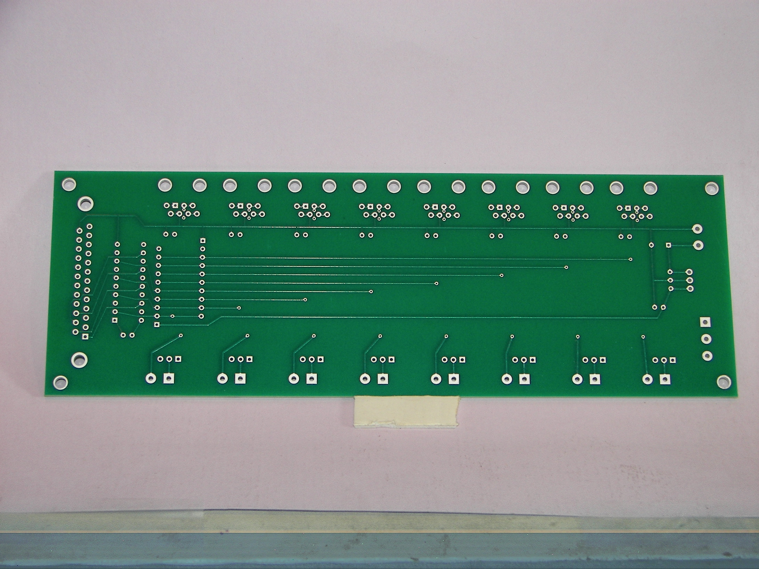
 Back side
I designed an add-on circuit that could be plugged into the same cable (using a ribbon cable, with two connectors at the I/O board end, a couple inches apart.) To make it convenient, I contacted the Kit-74 manufacturer and got the board dimensions and mounting hole placement, so my board could be stacked with spacers directly on top of the K74.
Another goal was to make the whole system easily connected to my sensors and actuators. I was tired of screw terminals and 2-pin Molex plugs, and wanted something more modular. So ... I went with Telco-style modular jacks. I figured I would use two conductors for sensor input to the PC (mat switch, PIR relays, etc.) and have two other conductors to supply power to a sensor (PIR or beam-breaker.)
As that idea started to come together, I realized it would be nice to have a similar set of jacks for actuators, instead of wiring 120 VAC through the Kit-74 screw terminals all the time. So, another board, the same size, with 8 similar modular jacks, that could be wired to the Kit-74 - just once - and the actuators could be plugged in at will.
With a little planning, I was able to make just one PCB design that could be used for either an Input Buffer or an Output Connector board. With two blank PCBs and the right components stuffed, all three boards could be stacked up and packaged neatly...
Note that the totals listed include all optional components.
For the Input board, you most likely will not need the 2nd resistor network for a "pull-down". The input caps, C4-11 are also optional, but they're pretty inexpensive...
For the Output board, I included screw terminal blocks to connect to the Kit-74 relay terminals. You can just as easily use wires to jumper the boards together, for a $12 savings.
Both board configurations include 3-pin jumper headers, to permit individual selection of either of two power sources (say 120VAC and 24VAC) for sensor (inputs) or actuator (outputs) power. Again, if you're not frequently changing, or only have one voltage in use, wires work just fine.
The input or output connectors, J3-10, can be either RJ-11 (Telco style) or RJ-45 (Ethernet). The two DigiKey parts will fit the same pin pads. If you choose to use the RJ-45 connectors, you will probably need to slightly elongate the two board-lock holes to wider slots, to let them snap into place (~0.025" each.)
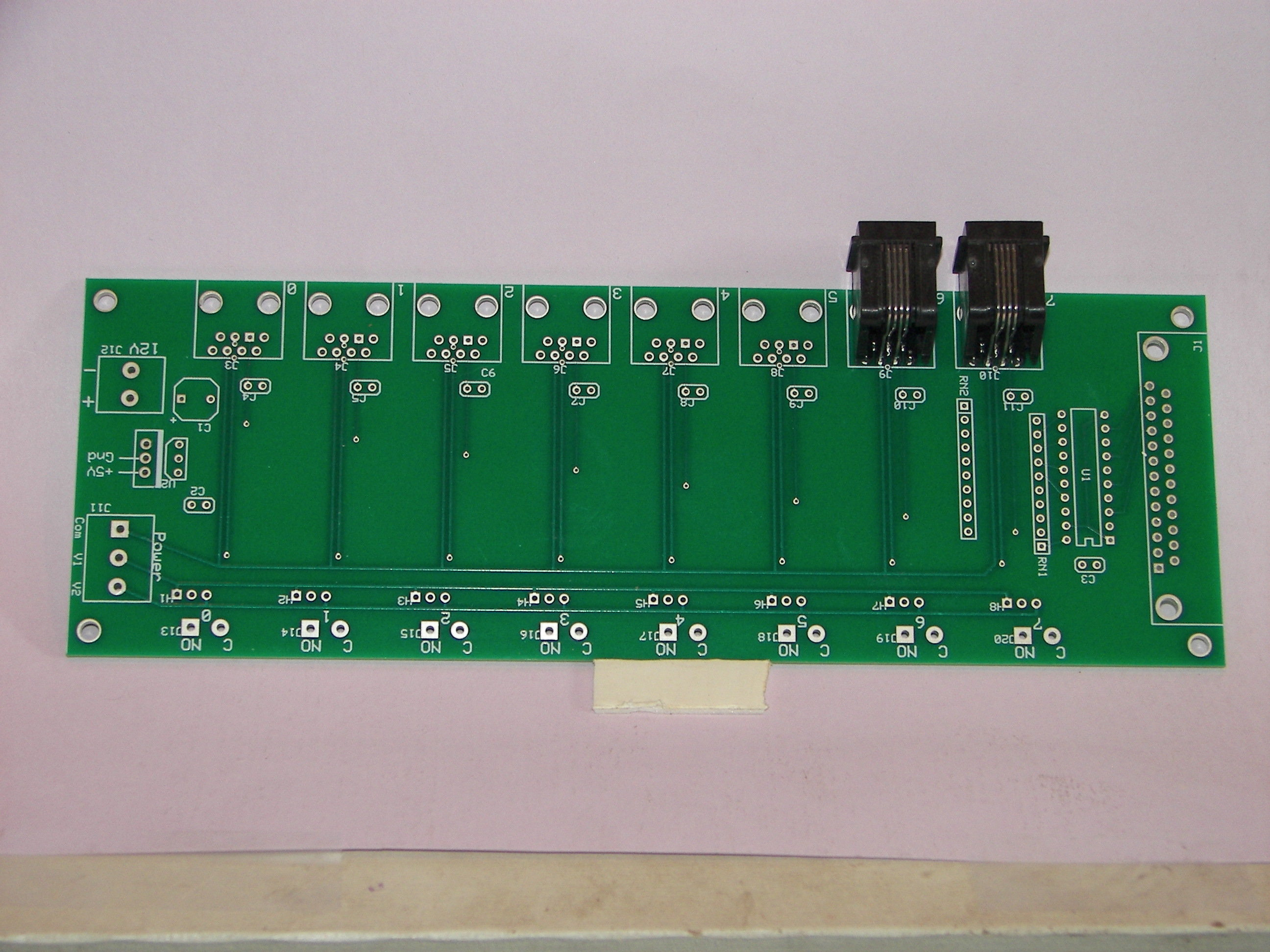
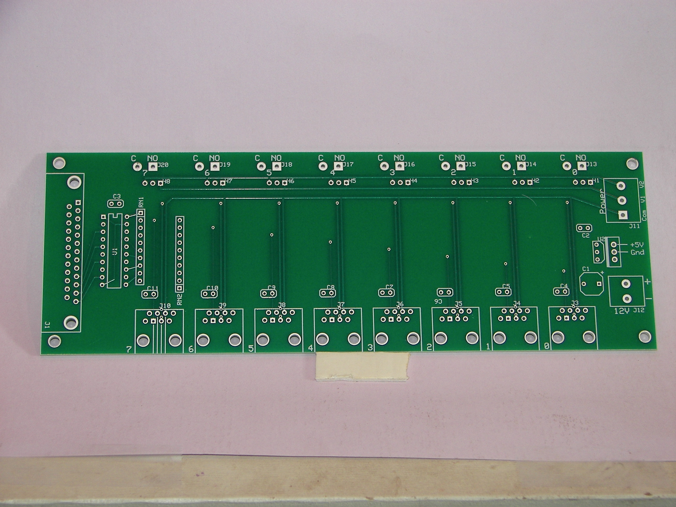 Component side
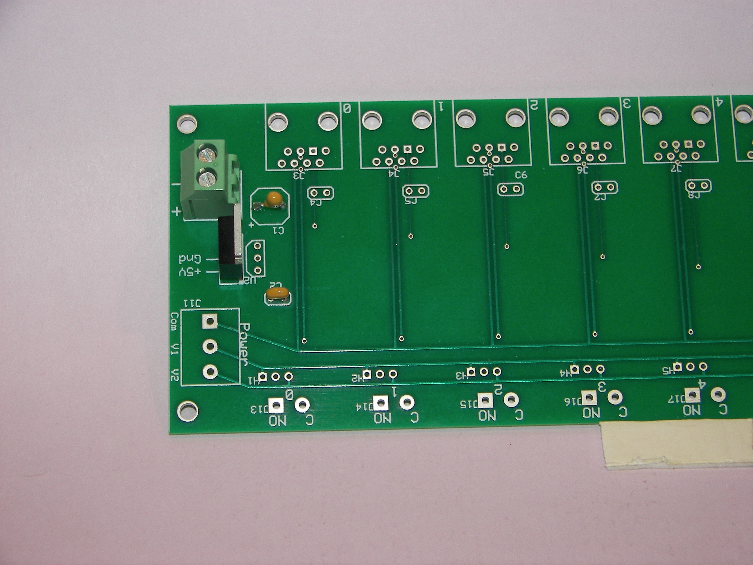 Power supply assembled and checked out
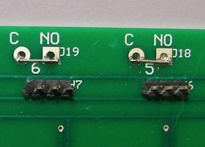 Input bd: Relay pins jumpered detail
Created on ... April 14, 2008
Last updated on ... May 24, 2008
 RJ11s test fit
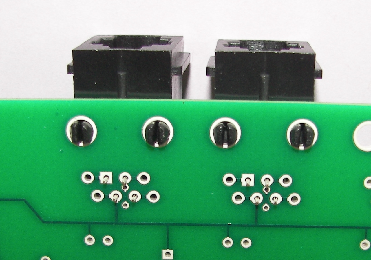 RJ11 boardlocks detail
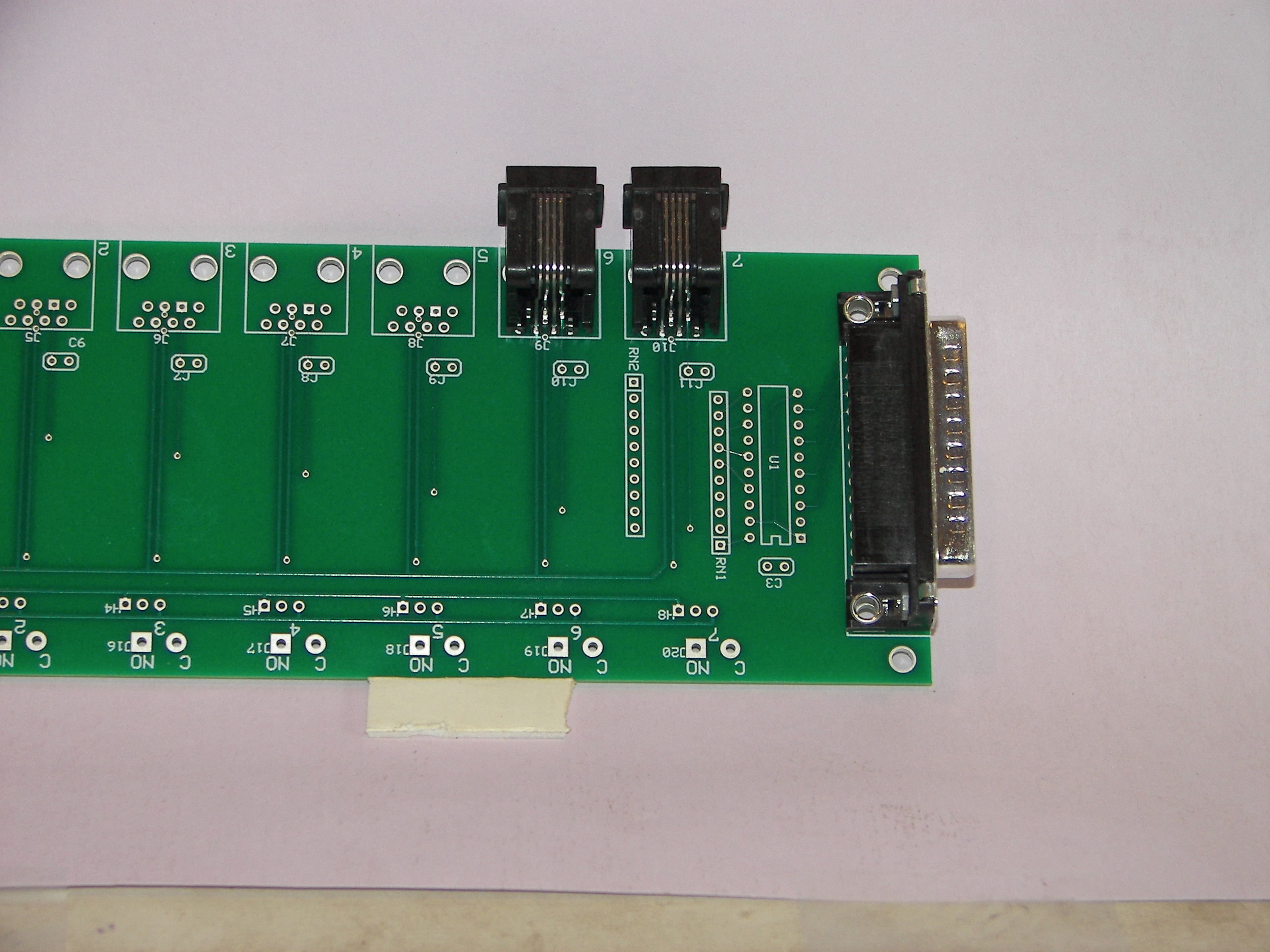 DB25 fitted
 Nearly all assembled