Modification notes for:
Regent Model MS-35
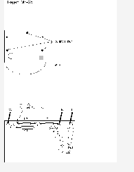
(See bottom view, Figure 1)
Remove small Phillips screw, deep in 1/8" holes.
(See PCB drawing, Figure 2)
1) Remove three components:
R1, R2, C1 (large, red-brown, rectangular)
2) Remove Black wire, and reattach at {A}.
3) Add a new Red wire at terminal where Black lead used to be.
Thread new wire out through knuckle parts (will need to remove
small screw holding knuckle together, temporarily).
4) Reassemble:
Slide PCB into housing, ensuring it slips between card guides.
Connections:
Black - Power return.
White - Power high
Red & Red - Isolated output contacts:
240 VAC / 10 Amp
120 VAC / 20 Amp
24 VAC / 10 Amp

