      An Experimental Cross-Fader for Pepper's Ghost
      ==============================================

I pulled apart a simple rotary light dimmer from Home Depot ($3.99)
to see if it could easily be modified to make a cross-fader. All
the basic components needed for one dimmer channel are there, and
taking the "guts" from another similar dimmer, we should be able
to make one control fade from one output to the other.

I quickly realized that I would also like to have a Master control,
that would turn the entire system up full, or dimmed down. That
would set the maximum level for the 'ON' channel, and the fader
would go from there to 'OFF'. Since the dimmers come with switches
on the control pots, I could keep the switch on the Master pot, to
turn the whole thing fully off...

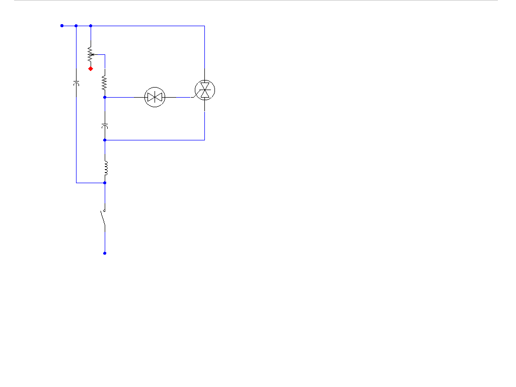
The file "Dimmer.gif" is the schematic of the original dimmer as
I found it. Obviously, some units will be wired a little differently,
but the basics are usually all the same.

The variable resistor is the dimmer control, and is wired to make a
voltage divider, along with the series fixed resistor and the capacitor
just below them. The voltage across the cap is switched by the trigger
diode and fires the gate of the TRIAC on the far right. That device
is what passes the current to the load, varying the effective output
according to the pot position.

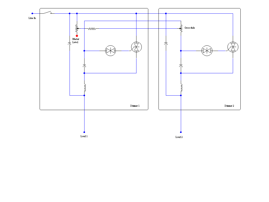
Combining two dimmers, we get the schematic in "Fader.gif". The line
input is wired through the Master control's switch terminals, and
feeds power to both dimmer circuits. The Master pot's output is wired
not to it's own capacitor/trigger/TRIAC circuit, but feeds the SLIDER
of the Fader control's pot. One end of the Fader pot wires to each of
the dimmer circuits. (Note that the extra series resistor is left out.)

As a result, the Master pot adds series resistance to both dimmers,
and the Fader pot distributes the signal to each dimmer.

Mount both dimmer units in a 3-gang electrical box, along with a
grounded, duplex outlet. On the 'hot' side of the outlet, there is
a little brass tab, connecting the two outlets together. Normally,
in a house, you would leave this alone; here, we break the tab off,
isolating the hot sides of the two outlets. The 'neutral' and
'ground' pins stay common. (The 'hot' pin is the smaller blade-
shaped hole, by the way, and has copper-colored screws and tab. The
'neutral' side has silver parts.) The two 'Load' wires from the
dimmer circuits go to the separate 'hot' screws on the outlets. The
hot side of the line cord (black wire) goes to the common 'Line In'
lead in the schematic, and the green 'ground' wire should tie to
the grounding screw on the side of the outlets. If the box you use
is steel, that will also tie the ground to the dimmer plates, and
minimize any chances of getting shocked off the knobs.

Some experimentation may still be required, to make it all work
over a full brightness range, and fade smoothly. Get two of the
same dimmers to make them act as much alike as possible, and I'd
really suggest using new ones.  I'll post more here as I work with
the unit, and as others may report their results!
(Click on drawings for a larger, more legible view!)
 Original dimmer circuit
 Combined fader circuit
 Original dimmer circuit
 Combined fader circuit